How COOL is THIS: Intercooler Pressure versus Pump Output and Flow @Motorama

Update:

Although the info shown is relevant for 4 Laminova cores in series, the Cadillac design does not have 4 in series but rather has A-B in parallel and C-D in parallel flow.  I caused some confusion in the way I asked my question of Laminova as it turns out.  I am leaving this for consideration, but the pressure head through 2 Laminova cores instead of through 4 cores would be different.


Intercooler coolant pumps are at heart 12v water pumps.  Extra points if they are light and quiet, and very long lasting.  They are rated in gallons per minute, or liters per minute, or liters per hour.  However, with pumps one also has to know at what pressure.  If an 8 gpm pump is pumping against NO resistance then it can pump 8 gpm of fluid.  However, if it is pumping against some resistance, like the four cores of a STS-V intercooler, it has a harder job and the flow rate will drop.

Laminova was kind enough to send me this graphic showing pressure versus flow through four Laminova cores sized for the Cadillac STS-V application in serial:

Below is a graph with heat transfer vs. flow rate for a 4 x 39.5 mm cores in 392 mm length, coolant in series over the cores. (calculated with 350g/s 110ºC for the charge air, 30ºC coolant with flow from 10 to 35 l/min). As you can see performance continues to increase with increased flow, but at 35 l/min you have almost 1,4 bar pressure drop, then add the radiator etc. So be careful when choosing pump, normally there are graphs for flow vs. backpressure for the pumps available.

Laminova Cores bar of pressure vs lpm of flow

Let’s examine this graphic.  First, a bar of pressure is a bit less than the English atmosphere (A), so 1 atm (atmosphere) = 1.01325 bar.  Let’s stay in bar for now, as it is frequently used for discussion of our topic.  But when you read bar you can think 14.5 psi if you prefer.  A liter per minute is 0.2642 gallons per minute (gpm).

What the graphic shows is that as the coolant flow increases from 10 lpm (2.6 gpm) to 35 lpm (9 gpm) the pressure required to push the water through the 4 STS-V Laminova intercooler cores increases from 0.15 bar (2.1 psi) to 1.4 bar (20 psi).  It takes a LOT of pressure to reach a 9 gpm flow rate.  The good news is the heat transfer for the system of cores continues to improve right up to 9 gpm, flattening out after that rate of flow.

If we could increase the flow rate from 16 lpm (4 gpm) up to 35 lpm (9.2 gpm), the heat transfer will increase from around 16 kw up to around 22 kw, or 38% more intercooling at max rate.

It is inviting to think then, that the STS-V 8 gpm intercooler pump is about right on the money; unfortunately, that pressure it has to pump against lowers its output quite a bit.  Let’s see how much.

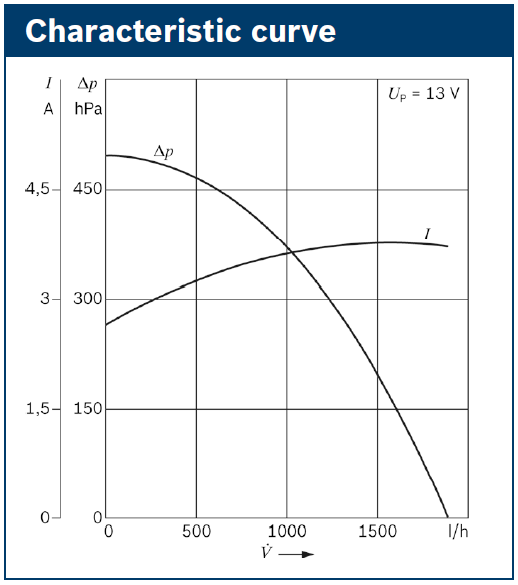
The Cadillac STS-V uses a Bosch sourced 8 gpm (gallon per minute) pump.  Here is a diagram of the Bosch pump output:

Bosch Intercooler Pump Flow vs Pressure

This diagram introduces new units again, but we’ll get through it.  Along the x axis we have Volume of flow in liters per hour.  Along the y axis we have delta pressure in hPa, which is hectopascals of pressure.  1000 hectopascals  = 1 bar.

So this Bosch pump will flow 0 liters per hour at 0.5 bar, and up to 1800 liters per hour (30 lpm, 7.9 gpm) at no pressure.  Good, as it is rated for 8 gpm.

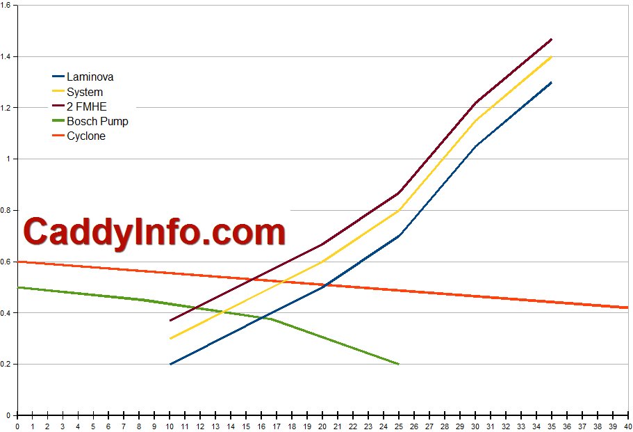
Now, how do we determine how much a Bosch pump in our STS-V would flow against the pressure through the intercooler, hoses, and heat exchanger?  We graph them together based on flow rates versus pressure and see where their graphs cross.   That will be the point where the flow rate of the pump against the resistance in the system is equivalent.

I have included the Jabsco 50840-12 Cyclone aftermarket intercooler pump for comparison as well, reading off their flow graphic.  This is a popular replacement intercooler pump for the STS-V.

Laminova System Cyclone Bosch Pump
FLOW L/Min Pressure bar Flow L/Min Pressure Bar Flow L/Min Pressure bar
10 0.20 0.3 0 0.6 0 0.5
15 0.35 0.45 40 0.42 8.33 0.45
20 0.50 0.6 80 0.2 16.67 0.38
25 0.70 0.8 120 0 25 0.2
30 1.05 1.15
35 1.30 1.4

This data table shows the resistance through the Laminova cores alone, then an equivalent resistance value for the whole intercooler cooling system.  I don’t know a good value for this so I used 0.1 bar or 1.4  psi of pressure to represent the intercooler heat exchanger (1 psi), hoses (0.4 psi), etc.  We can change it to another more accurate value later, and can model 2 heat exchangers, etc.

The data is really easy to relate to if we put each set on an XY graph, so let’s do that!

Calculated Flow Rates:

Cadillac STS-V Intercooler Flow Rate vs Pump Output & Pressure - Bar versus Liters per Minute

So reading from the graph, I find this tabular result:

Liters/Min Gallons/Min
Pump Core Only System Core only System
Bosch 16 13 4.19 3.41
Cyclone 20 18 5.24 4.72

In other words,  the 8 gpm Bosch pump will pump 4 gpm if it were only pumping through the 4 Laminova cores in serial (theoretical value), or 3.4 gpm through the whole system.

The higher flow Cyclone pump will or 4.7 gpm through the whole system, or 38% better than the stock pump.

A second FMHE (front mounted heat exchanger) might cost 1 psi and thus 2 lpm or 0.5 gpm of flow.  Also notable is that the Cyclone pump with a 2nd FMHE still probably flows more than the stock pump and single FMHE.  Heat transfer probably increases by 0.5 kw, or 38% of the increased flow rate of 1.3 gpm.

Ideas for further study:

Design an experiment to test actual flow rate through the system.  Ideal to me would be to add a flow rate indicator (gauge).

Source a replacement intercooler coolant pump that can pump 9 gpm against a 1.5 bar head pressure in order to optimize intercooler cooling.  This is likely to need to be a positive displacement pump rather than a centrifugal pump.

See an error?   Applause for the effort?  Chime in via the comments section!!

PIDs, FMHEs, Fans, and Intercooler Pump Flow Rates

I have a variety of topics today, but maybe they will all come together in the end.  If not, at least they will help me progress my thinking.

PIDS

The Society of Automotive Engineers (SAE) established a number of standard parameter identifiers (PIDs) so that as on-board diagnostics matured (OBDII) there would be  standard way to interface with an automobile and determine current status, parameters, etc.  Unfortunately, today the majority of PIDs in use by manufacturers are non-standard PIDs.  Further, instead of publishing the list of non-standard PIDs in use, the manufacturers sell their list to diagnostic equipment manufacturers.  That leaves small businesses out of the picture since they can’t afford to purchase the rights to the annual PID lists from multiple manufacturers.

I have been using the Harrison R&D CanScan interface and software to datalog the STS-V.  I need to monitor the intake air temperature sensor after the intercooler, IAT2, which unfortunately is a non-standard PID, and the software doesn’t have the hexidecimal code for that one.  HPTuners has done a lot of GM work with their scanning and tuning solutions.  I ordered a HPTuners VCM Scanner setup to use for datalogging.  It can be upgraded later to the full tuning suite if needed.

Once I can monitor the IAT2 temps then I can get more detailed logs of how my stock intercooler cooling system performs before considering any changes.

FMHE

Front mounted heat exchangers:  the popular under-bumper heat exchanger is a 26″ wide x 7″ tall x 3.5″ deep water to air heat exchanger that fits under the nose of the STS-V.  Scanning google it is also a popular add to other supercharged cars.  First, it retails for $179 which makes it affordable.  Second, it fits in a variety of applications.  Here is a link to the one at frozonboost.com:

FrozenBoost.com FMHE

Very little data on how efficient it is, but I have read a number of happy reports with good results.  Also, this one has been used in some current STS-V installations with good results.

Fans

One of my favorite FMHE solutions is the one at revanracing.com, which has dual puller fans behind a heat exchanger.  It is 26x12x4.5 (29″ wide with side mounts). Unfortunately although the width looks good the height is a bit tall for the STS-V nose where only 8″ is available.  I would like to add 2 puller fans to the 7″ tall FMHE but I am not sure there is room yet.  More study needed.

Pump Flow Rates

Another topic for discussion in intercooler cooling modifications is the flow rate for the intercooler pump.  The stock bosch-sourced intercooler pump on the STS-V is a centrifugal unit and flows 8 gallons per minute (gpm) or similar.  Some replacements claim flow rates of up to 30 gpm, which apparently can move the fluid through the core too fast to effectively remove heat.   This is something that would need more inputs for study — like temperature sensors at the in/out of the laminova intercooler system, and in/out of the heat exchanger and tests with datalogs in a variety of conditions.  I think for now I will leave this topic for later, and let others experiment in this area.  One of the features however of the 7″ FMHE is it has an easy place to put a temperature sensor.

On a separate note, at steady state driving the temperature change across a radiator is often only 10F.   The issue is how well the FMHE handles temperature transits such as wide open throttle induced sudden supercharger heat.

Summary

I am having a great time analyzing / studying the various engineering issues around intercooler cooling, and the body of work that people have done to test and install improved cooling solutions on their vehicles.  I think the important thing is to review it all, then setup an appropriate experiment and test, test, test.  That way we will have persuasive data on what works and what just costs money.  It is not lost on me that all of the changes people are making may make very little difference in the real world.  So my plan in general is consider, research, design an experiment, test the stock setup, select a mod, mod, test the mod.  Hopefully that will yield persuasive data, and along the way make for interesting articles here on the blog.


Intercooler Cooling: Corvette ZR-1 LS9, Cadillac CTS-V LSA, & STS-V LC3

The Chevrolet Corvette ZR-1 has a supercharged 6.2L OHV V8 engine.  It uses a TVS2300 supercharger with an integrated fin-type intercooler.  I am interested in the other end of the equation for this discussion, the heat exchanger.  Let’s look at how the Corvette design differs from my 2008 STS-V, and the 2009 CTS-V.

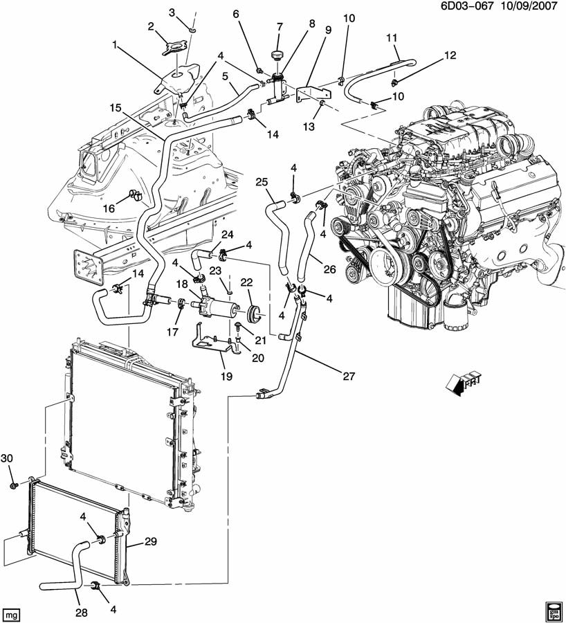
From our previous discussion, here is the intercooler cooling system for the 2008 STS-V:

STS-V LC3 Intercooler Flow path & Parts

Coolant flows from the output of the intercooler at the top of the engine through 26 and 27 to the front mounted heat exchanger 29.  After a pass across the heat exchanger, it flows to the intercooler pump 18 and then up via 25 to the intercooler at the top of the engine again.  There is a T along the way between 14 & 17 that allows for an up-pipe leading to a small reservoir and used for filling of the system.

It is not clear to me for the STS-V front-mounted heat exchanger how many ‘passes’ it contains.  Fluid enters at the top right and leaves at the bottom left, and may snake a few times across the fins of the heat exchanger on the way.  The GM p/n is 25770419 for the STS-V heat exchanger.  The heat exchanger on the car is not clearly visible for investigation.

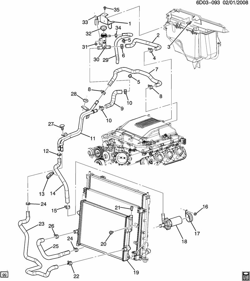
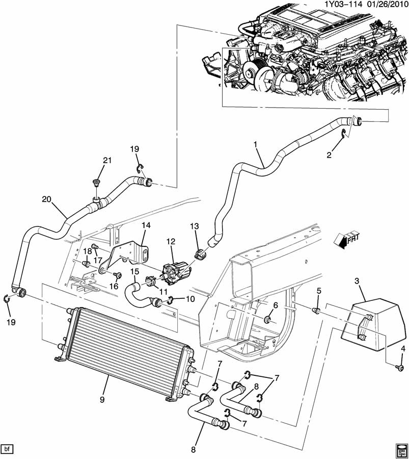
We find a similar system on the 2009 CTS-V LSA engine.  The LSA is a supercharged 6.2L OHV V8 similar to the ZR-1’s LS-9 engine, except that it uses a TVS1900 Supercharger and has different internals.  As we will see, it also uses a different intercooler cooling strategy:

CTS-V LSA Supercharged V8 Intercooler cooling system

Here we see coolant flows from the intercooler at the top of the engine through 2 and 9 into the right or bottom side in our view of 11, then into 23 to reach the front-mounted heat exchanger 19.  After one pass across the heat exchanger, the cooler coolant flows out through 25 to the coolant pump 18, and via 14 back through the other side of 11, and along 7 back to the intercooler at the top of the engine.  Like the STS-V system, a T in the line at 30 just in from 2 allows fluid flow from the small reservoir and filling of the system.

The GM p/n is 25876663 for the CTS-V Coupe heat exchanger.

Mods: when modifying the CTS-V heat exchanger, D3 and Lingenfelter replace the stock one with a larger example.  Wait4me adds a second heat exchanger in front of the stock heat exchanger.

Now let’s look at the Corvette ZR-1’s LS-9 V8 system solution:

ZR-1 Intercooler System flow

Here we see the intercooling coolant flow into the front mounted heat exchanger.  Note that the front mounted heat exchanger is a 2-path heat exchanger.

Hot coolant flows from the intercooler at the top of the engine to the top row of the front mounted heat exchanger, and across the heat exchanger and into a inline reservoir.  From the inline reservoir cooler coolant flows back into the front mounted heat exchanger, then to the intercooler pump.  From the pump the cool coolant heads to the intercooler at the top of the engine.

The front mounted heat exchanger is p/n 20759871.  Yes, these three applications use 3 different front mounted heat exchangers.  Although there may be inherent benefits to the Corvette approach, it is also possible that due to packaging limitations in the Corvette there was simply less room available to use the larger area heat exchangers in the Cadillacs.

The STS-V system holds 2.6 quarts (2.5L) of coolant; the CTS-V holds 3.2 quarts (3.0L) the Corvette system holds 5.2 quarts (4.9L) of coolant.  Additional coolant in the system acts as a time buffer for changes in temperature of the system.  So when the coolant is heating up like wide open throttle from idle, then it takes longer to heat up.  However, when the coolant is cooling down like when high speed is pushing cold fresh air across the heat exchanger, it would take longer to cool down.

The pump in the Corvette is apparently different also; that’s a $1K pump where the one in the STS-V is under half that.

Ideas for Discussion:

Could the Corvette’s 2-pass heat exchanger and reservoir be easily adapted for use in the STS-V? Should it be? Only adding the reservoir might be an option, to boost the STS-V coolant capacity to near the ZR-1’s.

Does the STS-V NEED more intercooler coolant capacity?  I appreciate that it helps for back to back dyno runs, but on an actual drive there is high speed wind over the intercooler heat exchanger to compensate for the higher temps, and being able to quickly cool the intercooler coolant might be an advantage on the street.

Adding a second heat exchanger for the STS-V in front of the current heat exchanger would add fluid capacity and something less than twice the cooling, and be relatively easy to plumb.  However, it would require more experimental design to capture temps going in and out of the current heat exchanger under a variety of conditions, then in and out of the doubled heat exchanger in a variety of conditions.  The net effort might be less than worthwhile for the net benefit.