CaddyInfo Cadillac Chat 2015-09-17


Topics:

  • Platform names
  • Cadillac XT5 — Does Cadillac need a high performance Battery electric vehicle Tesla Competitor?
  • Intercooler coolant temperature control
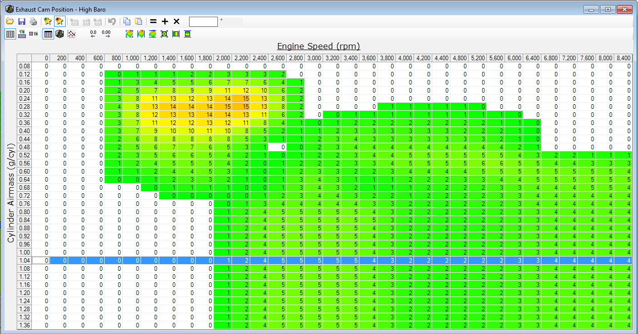
  • Programming VVT on the Cadillac LC3

After the chat I redid the analysis of cd 0.31 vs cd 0.33 and determined only 1 whp delta, but playing with loading different profiles showed me something was wrong with my default profile.  Here is a comparison showing Tune 6F if the XLR was 0.31 vs 0.33 cd:


xlr comparison of different CD 031 vs 033

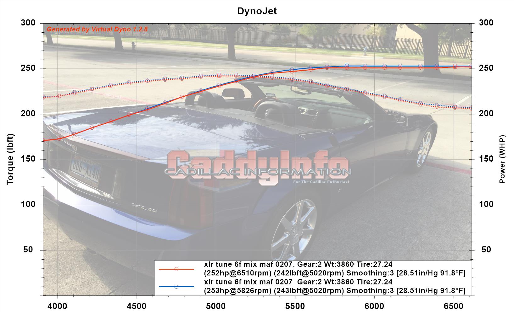
What we see here is the Tune 6F at 0.31 coefficient of drag in red, and the same data except CD 0.33 in Blue.  The blue is 1 whp better.  All other setting identical.

Note that with the profile fix or re-ordering, Tune 6F is now registering at 252 whp not 241 whp with the previous default profile.  Unfortunately, now that I reloaded the profiles to get the CD test to work, I can’t ‘go back’ to the broken default profile to understand what was different about it.

Additionally, I created this graph to compare Virtual Dyno output to calculated torque & hp:

XLR Tune 6F Compare Calc HP to VDyno Output corr

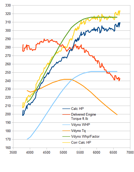
The blue and red lines are the calculated torque and hp. The high yellow line is the corrected hp for atmospheric conditions.  The orange and light blue lines are the virtual dyno w-torque and whp.  The Green line is the Virtual Dyno line with a factor applied to move it up to the calculated hp.  The green line is a smoothed line (average of averaged of values) but appears to be a good fit for the calculated hp curve.  This surprises me as I was thinking that the virtual dyno and the calculated hp frequently do not follow one another based off of the detailed data.

There is still some additional losses in both sets of data from running the test in 2nd gear instead of a 1:1 gear.  The XLR doesn’t have a perfect 1:1 gear, but testing in 2nd is a trade between smooth data, safe testing, and mechanical losses.


Nordic Ice and the AVS Intercooler Tank

We receive some meds packed in thermal blankets with Nordic Ice gel packs tucked in to keep them cold.  “freeze and re-use as long-lasting ice packs” they say.  I have a hot intercooler coolant system (most any day).  What happens if we put these two ideas together?

ice1

In my intercooler system, coolant flow up from the pump to the intercooler, then down to a heat exchanger, through a reservoir, another heat exchanger, and back to the pump.  Almost none of the system is accessible with the nose of the V in place.

However, if I remove the engine covers and gently pry back the air guides, I can just slot in Nordic ice bags on the AVS aluminum coolant tank.

ice2

I had extras so I put them near the filter to try to provide some local A/C.

temps over time

The yellow line is ambient temp in the driveway — yes 100F here in Texas.  The blue line is air into the engine intake — around 120F.  The Red line we would like to see go down to below 100F (wishes).  What we see is that it falls from 148F to a flat steady 138F and stays there regardless of the iced tank.

seal

I did discover that there was radiator air leaking into the filter area near a joined metal location and applied a seal there to block hot air coming to the filter.

Conclusion

The test was not ideal, as no air was flowing over the two heat exchangers since the V was sitting with the engine running in the driveway.  I was hesitant to drive with the Nordic Ice packs just loosely stacked on the AVS tank.  However, I could in a future test add a fan over the heat exchangers.

It would be great to engineer a system to allow ‘transfusion’ of cold intercooler coolant into the system when heat soaked and thus restore it to cold temps for testing.

VVT Tuning & Info for the Cadillac STS-V LC3 V8

I plan to update this page with notes on variable valve timing tuning for the LC3 DOHC VVT Supercharged V8 in the STS-V.

highbaro_vvt_intake

HPTuners Table — Intake Cam position

highbaro_ExhaustCamPosition

HPTuners table — exhaust cam position

Cam Phasers: [ref]
Intake: Initial timing 133 degrees ATDC with 40 degrees advance authority
Exhaust: Initial timing 117 degrees BTDC with 50 degrees retard authority

Valve Lift: Intake: 10.5mm (.413 inch)
Exhaust: 10.0mm (.394 inch)
Duration @ .050″
Intake: 202 degrees
Exhaust: 214 degrees

VALVETRAIN VARIATIONS
One of the key elements in achieving the broad output of the LC3 is the variable valve timing (VVT) system. With VVT, the seemingly opposed objectives of smooth and torquey low-end output, and massive specific output to a peak at 6400 rpm become possible, using individual hydraulically actuated phasers on each of the four camshaft. “Four-cam VVT is an exceptional performance enabler, but also provides the control flexibility needed for highly advanced NVH and emissions characteristics,” said Dave Caldwell, Northstar V-8 SC development and calibration engineer. “The supercharger module and VVT system complement one another, resulting in a genuine luxury and performance engine.”

This system allows the camshaft phasing to be altered in relation to the piston position, as well as in terms of event timing between the intake and exhaust camshafts. The VVT system was introduced last year on the normally aspirated Northstar 4.6 liter V-8, and the system received all-new command strategy optimized for the supercharged 4.4 liter application. The variable valve timing system makes it possible to target optimal idle quality, control cylinder pressure and detonation, and enhance drive-ability, while providing for the high-speed breathing necessary to turn a number at the top of the power band. Another advantage of the system is a reduction in exhaust emissions, which effectively eliminated the need for supplemental emissions equipment in the form of air injection or exhaust-gas recirculation systems while meeting today’s stringent emissions standards.

Simple cam tuning rules for BOOSTED engines: [ref]

  • Advance intake and exhaust => more low-RPM power, less high-RPM power
  • Retard intake and exhaust => more high-RPM power, less low-RPM power
  • Less overlap => lower EGTs, faster turbo spool, less fuel
  • More overlap => higher EGTs, slower turbo spool, more fuel
  • Conclusion: Advance Both at Low RPM, Retard both at High RPM

What is happening in the VVT cam programming for the LC3:

Intake:  From 3200 to 6400 RPM, position set at 20 degrees
Exhaust:  At low RPM position set at 5 degrees, decreasing to 2 degrees at mid and back to 5 degrees at high RPM

The VVT strategy the factory tune is using seems odd — the hope of VVT is to change the position of the valve timing from low (3200) rpm to high (6400) rpm, but the system appears to command a similar intake (20) and exhaust position (5) for both rev ranges.  The conventional wisdom for boosted engines is more advance for both at low RPM and more retard for both at high RPM.

Challenge:[ref]

The challenge of tuning a motor with VVT is that every change of the cam timing must have a corresponding change to the ignition timing and fuel tables. In one example, a change to the cam timing caused the PCM to enter a different cell on the spark table, which killed the timing and power in the mid to upper rpm as the result.

Feedback

What do you think?  Why did the factory take this strategy?