The Chevrolet Corvette ZR-1 has a supercharged 6.2L OHV V8 engine. It uses a TVS2300 supercharger with an integrated fin-type intercooler. I am interested in the other end of the equation for this discussion, the heat exchanger. Let’s look at how the Corvette design differs from my 2008 STS-V, and the 2009 CTS-V.
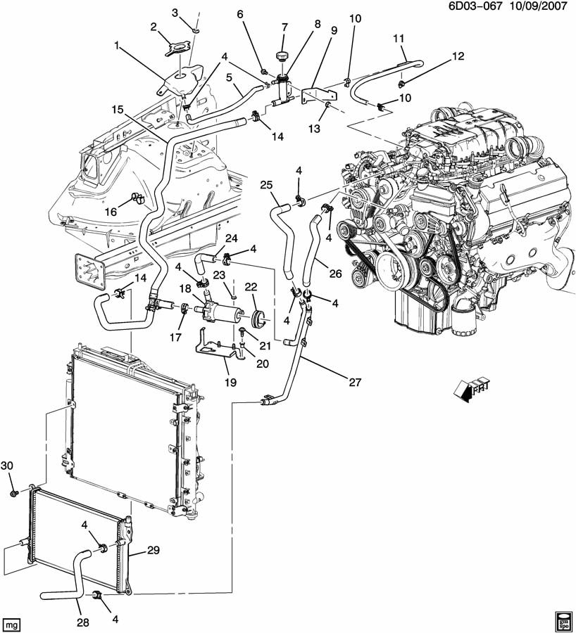
From our previous discussion, here is the intercooler cooling system for the 2008 STS-V:
Coolant flows from the output of the intercooler at the top of the engine through 26 and 27 to the front mounted heat exchanger 29. After a pass across the heat exchanger, it flows to the intercooler pump 18 and then up via 25 to the intercooler at the top of the engine again. There is a T along the way between 14 & 17 that allows for an up-pipe leading to a small reservoir and used for filling of the system.
It is not clear to me for the STS-V front-mounted heat exchanger how many ‘passes’ it contains. Fluid enters at the top right and leaves at the bottom left, and may snake a few times across the fins of the heat exchanger on the way. The GM p/n is 25770419 for the STS-V heat exchanger. The heat exchanger on the car is not clearly visible for investigation.
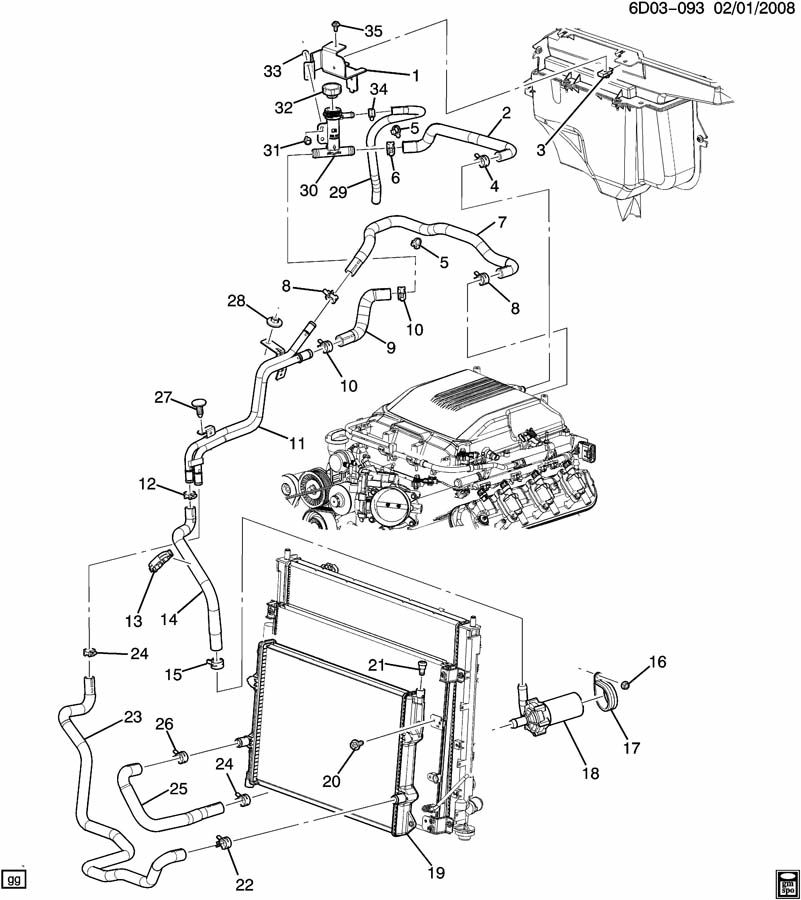
We find a similar system on the 2009 CTS-V LSA engine. The LSA is a supercharged 6.2L OHV V8 similar to the ZR-1’s LS-9 engine, except that it uses a TVS1900 Supercharger and has different internals. As we will see, it also uses a different intercooler cooling strategy:
Here we see coolant flows from the intercooler at the top of the engine through 2 and 9 into the right or bottom side in our view of 11, then into 23 to reach the front-mounted heat exchanger 19. After one pass across the heat exchanger, the cooler coolant flows out through 25 to the coolant pump 18, and via 14 back through the other side of 11, and along 7 back to the intercooler at the top of the engine. Like the STS-V system, a T in the line at 30 just in from 2 allows fluid flow from the small reservoir and filling of the system.
The GM p/n is 25876663 for the CTS-V Coupe heat exchanger.
Mods: when modifying the CTS-V heat exchanger, D3 and Lingenfelter replace the stock one with a larger example. Wait4me adds a second heat exchanger in front of the stock heat exchanger.
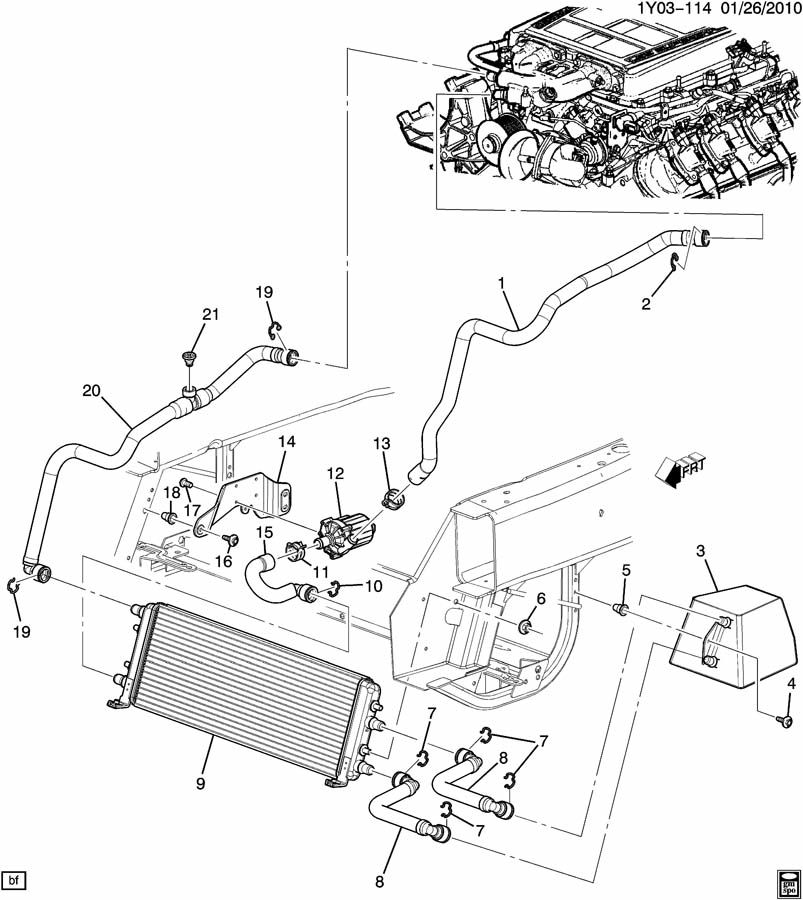
Now let’s look at the Corvette ZR-1’s LS-9 V8 system solution:
Here we see the intercooling coolant flow into the front mounted heat exchanger. Note that the front mounted heat exchanger is a 2-path heat exchanger.
Hot coolant flows from the intercooler at the top of the engine to the top row of the front mounted heat exchanger, and across the heat exchanger and into a inline reservoir. From the inline reservoir cooler coolant flows back into the front mounted heat exchanger, then to the intercooler pump. From the pump the cool coolant heads to the intercooler at the top of the engine.
The front mounted heat exchanger is p/n 20759871. Yes, these three applications use 3 different front mounted heat exchangers. Although there may be inherent benefits to the Corvette approach, it is also possible that due to packaging limitations in the Corvette there was simply less room available to use the larger area heat exchangers in the Cadillacs.
The STS-V system holds 2.6 quarts (2.5L) of coolant; the CTS-V holds 3.2 quarts (3.0L) the Corvette system holds 5.2 quarts (4.9L) of coolant. Additional coolant in the system acts as a time buffer for changes in temperature of the system. So when the coolant is heating up like wide open throttle from idle, then it takes longer to heat up. However, when the coolant is cooling down like when high speed is pushing cold fresh air across the heat exchanger, it would take longer to cool down.
The pump in the Corvette is apparently different also; that’s a $1K pump where the one in the STS-V is under half that.
Ideas for Discussion:
Could the Corvette’s 2-pass heat exchanger and reservoir be easily adapted for use in the STS-V? Should it be? Only adding the reservoir might be an option, to boost the STS-V coolant capacity to near the ZR-1’s.
Does the STS-V NEED more intercooler coolant capacity? I appreciate that it helps for back to back dyno runs, but on an actual drive there is high speed wind over the intercooler heat exchanger to compensate for the higher temps, and being able to quickly cool the intercooler coolant might be an advantage on the street.
Adding a second heat exchanger for the STS-V in front of the current heat exchanger would add fluid capacity and something less than twice the cooling, and be relatively easy to plumb. However, it would require more experimental design to capture temps going in and out of the current heat exchanger under a variety of conditions, then in and out of the doubled heat exchanger in a variety of conditions. The net effort might be less than worthwhile for the net benefit.


