Adding boost pressure to the LC3 4.4L DOHC VVT V8

The Cadillac STS-V (2006-2009) uses the 4.4L supercharged Northstar engine, making 469 hp and 439 ft-lb of torque.  Can it make more?

Cadillac used a modified variant of the Magnuson MP122, or Eaton M122 supercharger, with a integrated intercooler using Laminova cores.  The powerplant was designed specifically to be supercharged.  The stock LC3 V8 uses 12 psi, or pounds per square inch, of supercharging.  In other words, if atmospheric pressure is 14.7 psi, then air flooding into the LC3 at maximum pressure is 14.7 + 12 psi = 26.7 psi.  In supercharger terms, it is at 26.7 / 14.7 = 1.82 pressure ratio.

As a rule, 1 psi of supercharging makes 4% more horsepower.  Technically, 14.7 psi of supercharging would make 100% more power, or 6% per PSI.  But, with inefficiencies, 4% per PSI is an achievable thumbrule.  Looking at this backwards, one might find that a non-supercharged 4.4L V8 would have made 316 hp.  This is very close to the 320 hp rating of the 4.6L VVT DOHC normally aspirated Northstar; no surprise.

So what would happen if we increase the boost level on the LC3 V8 from 12 psi up to say 14 psi or 17 psi?  Notionally, in a perfect world the 469 hp stock would increase to 492 hp at 14 psi, or to 530 hp at 17 psi.  However, there are issues to be considered such as the capability of the supercharger to make that much pressure efficiently, as well as the capability of the intercooler to take away additional heat produced.

A popular way to increase the output pressure of a supercharger is to substitute a smaller pulley for one or the other end or both ends of the supercharger pulley drive.  For the STS-V LC3, the crank pulley appears to be 5.88″ outer diameter, and the supercharger snout pulley is 2.8″ outer diameter.  Actually, I know the snout pulley diameter of 2.8″, and Cadillac said that the ratio between the two was 2.1:1.   Also, when D3 created a 10% overdrive pulley, they chose to make it 6.47″ outer diameter, which is 10% more than 5.88″.  This strikes me as an odd outer diameter, but note 5.9″ = 15 cm, so perhaps the crank pulley is metric?

Another choice is to change the supercharger snout pulley from 2.8″ to 2.55″.  Remember our ratio — crank:snout pulley ratio so 5.88:2.8 stock = 2.1:1

If we change the crank pulley to 6.47″, then the pulley ratio changes to 6.47 :2.8 = 2.3.  Now 2.3/2.1 = 1.1, or 10% faster, so 10% more boost, or 1.2 psi increase.

Likewise, a 2.55″ snout pulley would be 5.88:2.55 = 2.3 and 2.3/2.1 = 1.1 or 10% faster, so 10% more boost, or 1.2 psi increase.

Either way, 1.2 psi increase for 1.2 * 0.04 /psi = .048 or 4.8% increase.  So a 13 psi LC3 might increase from 469 hp at the crank to 491 hp at the crank or 24 hp.

In an ideal world then, another PSI of boost would also add another 24 hp.  For example, if we used a 6.47″ crank and 2.55 supercharger snout pulley for 6.47:2.55 = 2.5:1 ratio we could get to 2.537/2.1= 1.21 or 21% increase or 2.52 PSI. This would theoretically gain 47 hp and get from 469 to 516 hp.

A different approach is taken with the Stiegemeier Snake Bite kit.  By modifying the internal gearing on the supercharger, and porting and cleaning up the flow paths within the supercharger, up to 17 PSI of boost is produced with the stock/OEM supercharger snout pulley and crank pulley.    Theoretically this would gain 5PSI * 4%/PSI = 20% or 93 hp, boosting the LC3 from 469 to 563 hp.  However, again with real world inefficiencies the actual gain would be expected to be less.  I don’t see a claimed/measured gain on their website for this application.

So how do people get up to figures like 461 whp (wheel hp, or hp at the wheels on a dyno) or 576 crank hp (hp at the crankshaft on an engine test dyno) for the STS-V LC3?  Through a careful combination of a variety of modifications.

The actual boost the engine pulls has to overcome the intake resistance.  So add a higher flow intake and the engine effectively has more boost as a result.  Add more intercooler cooling and the engine can make and sustain more power.  Tune the engine for a specific car and environment and the engine can make more power.    Through careful tuning and multiple dyno runs the community and Professional Tuners have slowly pulled higher levels of performance from the LC3.

With the CTS-V release and adoption of the LSA supercharged 6.2L V8, there is less market for LC3 tuning and the focus has shifted to the newer cars.  That does not change the inherent goodness and balance of the 4.4L Supercharged LC3 engines, and I am having a great time considering and researching tuning approaches for mine.

HEY!

See anything you disagree with?  Did I get it ALL wrong? Do you agree and want to share your experiences?  Put a comment up and join the conversation!
PIDs, FMHEs, Fans, and Intercooler Pump Flow Rates

I have a variety of topics today, but maybe they will all come together in the end.  If not, at least they will help me progress my thinking.

PIDS

The Society of Automotive Engineers (SAE) established a number of standard parameter identifiers (PIDs) so that as on-board diagnostics matured (OBDII) there would be  standard way to interface with an automobile and determine current status, parameters, etc.  Unfortunately, today the majority of PIDs in use by manufacturers are non-standard PIDs.  Further, instead of publishing the list of non-standard PIDs in use, the manufacturers sell their list to diagnostic equipment manufacturers.  That leaves small businesses out of the picture since they can’t afford to purchase the rights to the annual PID lists from multiple manufacturers.

I have been using the Harrison R&D CanScan interface and software to datalog the STS-V.  I need to monitor the intake air temperature sensor after the intercooler, IAT2, which unfortunately is a non-standard PID, and the software doesn’t have the hexidecimal code for that one.  HPTuners has done a lot of GM work with their scanning and tuning solutions.  I ordered a HPTuners VCM Scanner setup to use for datalogging.  It can be upgraded later to the full tuning suite if needed.

Once I can monitor the IAT2 temps then I can get more detailed logs of how my stock intercooler cooling system performs before considering any changes.

FMHE

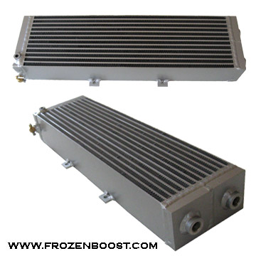
Front mounted heat exchangers:  the popular under-bumper heat exchanger is a 26″ wide x 7″ tall x 3.5″ deep water to air heat exchanger that fits under the nose of the STS-V.  Scanning google it is also a popular add to other supercharged cars.  First, it retails for $179 which makes it affordable.  Second, it fits in a variety of applications.  Here is a link to the one at frozonboost.com:

FrozenBoost.com FMHE

Very little data on how efficient it is, but I have read a number of happy reports with good results.  Also, this one has been used in some current STS-V installations with good results.

Fans

One of my favorite FMHE solutions is the one at revanracing.com, which has dual puller fans behind a heat exchanger.  It is 26x12x4.5 (29″ wide with side mounts). Unfortunately although the width looks good the height is a bit tall for the STS-V nose where only 8″ is available.  I would like to add 2 puller fans to the 7″ tall FMHE but I am not sure there is room yet.  More study needed.

Pump Flow Rates

Another topic for discussion in intercooler cooling modifications is the flow rate for the intercooler pump.  The stock bosch-sourced intercooler pump on the STS-V is a centrifugal unit and flows 8 gallons per minute (gpm) or similar.  Some replacements claim flow rates of up to 30 gpm, which apparently can move the fluid through the core too fast to effectively remove heat.   This is something that would need more inputs for study — like temperature sensors at the in/out of the laminova intercooler system, and in/out of the heat exchanger and tests with datalogs in a variety of conditions.  I think for now I will leave this topic for later, and let others experiment in this area.  One of the features however of the 7″ FMHE is it has an easy place to put a temperature sensor.

On a separate note, at steady state driving the temperature change across a radiator is often only 10F.   The issue is how well the FMHE handles temperature transits such as wide open throttle induced sudden supercharger heat.

Summary

I am having a great time analyzing / studying the various engineering issues around intercooler cooling, and the body of work that people have done to test and install improved cooling solutions on their vehicles.  I think the important thing is to review it all, then setup an appropriate experiment and test, test, test.  That way we will have persuasive data on what works and what just costs money.  It is not lost on me that all of the changes people are making may make very little difference in the real world.  So my plan in general is consider, research, design an experiment, test the stock setup, select a mod, mod, test the mod.  Hopefully that will yield persuasive data, and along the way make for interesting articles here on the blog.


Cadillac STS-V Optional Differential Cooler – Cool at a Price

Reading through old Techlink Articles I found this gem:

Differential Cooler

A differential cooler assembly is available for the Cadillac STS-V (fig. 1). The part number is 15868857.

The system is designed to reduce the operating temperature of the rear differential fluid when the STS-V is driven at extended high speed or in competitive driving. The STS-V comes with control logic to operate the system when high heat generation conditions are met. The wiring harness has provisions for the cooler, making it an easy installation. Installation time is less than 2 hours.

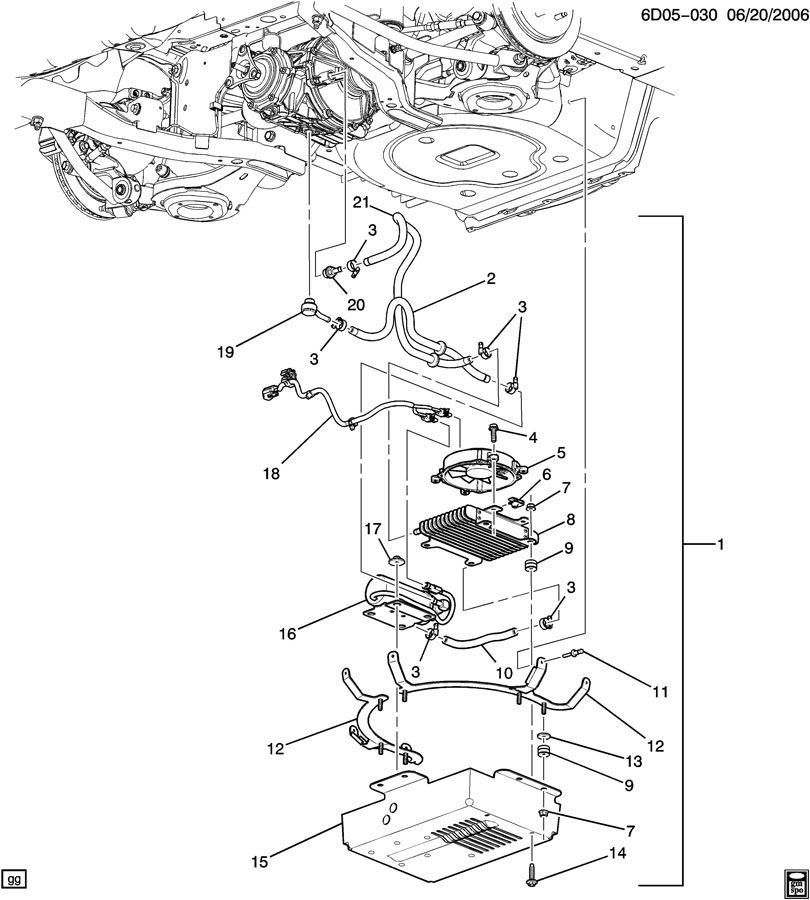
The differential lubricant pump and cooler assembly is located under the vehicle and is mounted to the rear storage compartment well. The cooler module assembly consists of a pump, a heat exchanger, an electric fan and assorted hoses/fittings. All components except the external lines and fittings are located in the Cooler Module.

Oil is pulled from the differential and pumped through a hose to the cooler/heat exchanger. The differential oil is cooled by dissipating heat as the 12 volt electric fan blows outside air over the heat exchanger. The cooled differential oil then returns to the differential.

TIP: The pump and electric fan can be turned on using the Tech 2 or suitable scan tool.

The differential cooler system has a maintenance feature that operates the system for approximately 15 seconds under certain conditions during initial vehicle operation. It is normal to hear the system run during this maintenance cycle.

If the vehicle is equipped with this system, rear differential fluid capacity is an additional 0.31 L (0.23 qt).

Okay, I definitely want one of these bolt-in babies for my STS-V, and I don’t see one hanging off my empty spare tire cover yet. Ouch, though — list price is a hefty $2,369, plus installation. Here is the parts diagram:

Cadillac STS-V differential cooling solution

Looks like a complete system for differential cooling, albeit priced around the cost of a differential?  GM put these on export models, as they might need to run at high velocity over extended periods (autobahn).  They are only considered additive for the US for track days.  The article suggests the circulating pump and cooling fan would run all the time.  An aftermarket solution plugging in the to the same in/out might be more affordable.  A similar kit for the gen 2 CTS-V is p/n 20792934.