For my upcoming Spectre Intake install the beauty cover on the LC3 4.4L DOHC VVT V8 in my 2008 STS-V will need to go. Technically, it can stay with less underpadding, but good excuse to remove it.
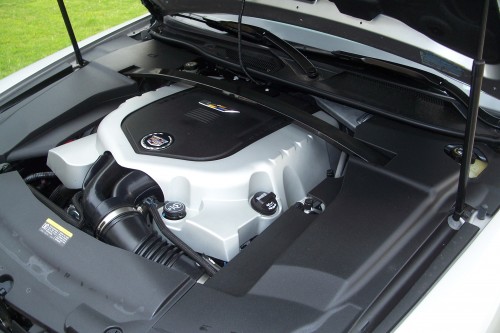
The top of the engine — the intercooler on top of the supercharger on top of the engine — is capped with this nice Cadillac beauty cover.
In my opinion, a beauty cover misses the point. I get that it cleans up the engine compartment nicely and all. But the beauty part should be the engine, not a molded cover hiding the engine.
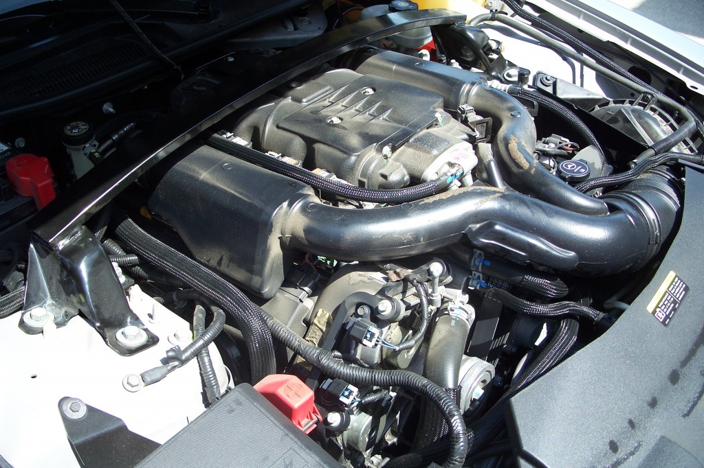
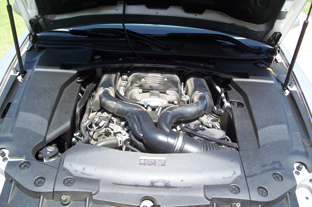
Here’s what it looks like with the covers removed: (click on images for larger versions)
With dirt, part of the underside of the foam from the beauty cover, et al.
This actually is MUCH more interesting to me, and you can see the air intake piping, the intercooler and cooling lines, and even down to the right the belt drive for the supercharger.
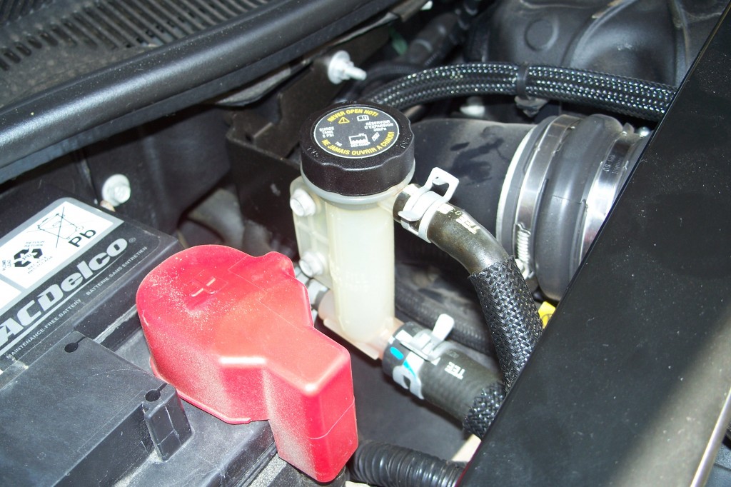
This is a close-up shot of the intercooler coolant reservoir. Yes, it looks like it is just a filler neck because that is what it is. The fill cold line is near or at the top of the tube. You can just see the actual coolant in the tube just at the bottom of the tube before the insulated covering.
The tube coming out of the top of the reservoir is a vent drain to an empty spot in front of the battery.
It strikes me that replacing this small tube with a larger but sized to fit in the space reservoir would add more fluid capacity to the system and if selected appropriately bolt in.
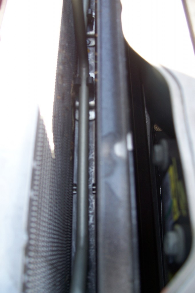
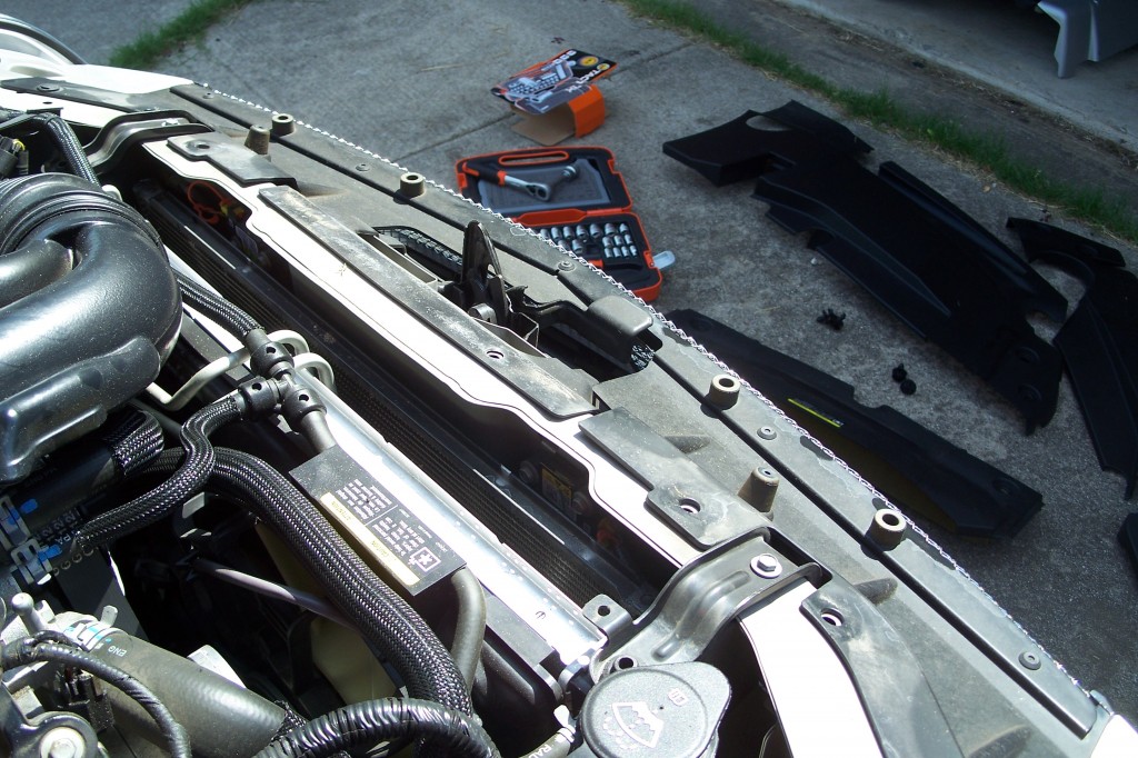
It is very hard to photograph the front heat exchangers, but here is a shot and bear with me because we’ll switch to diagrams after the photo:
There are three different heat exchangers in view at the front of the STS-V.
The are in order from back to front, 22 the radiator, 21 the transmission oil cooler, 19 the A/C condenser (CONDENSER,A/C ACDelco #15-63240), and 17 the intercooler front-mounted heat exchanger (FMHE), (RADIATOR,CHRG AIR CLR, 25770419).
So looking at that, this view looking forward in the engine compartment probably shows the item 19 (black); the intercooler heat exhanger is a smaller item ahead of that and not visible.
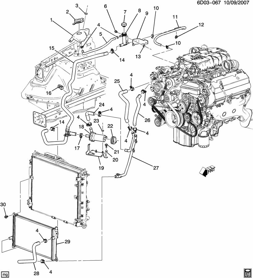
This diagram shows just the intercooler flow paths and parts:
This gives me pause — the assembly diagram shows a reservoir (1) and the line from the tube running to that reservoir. My STS-V does not have this item (1) at all, so I’ll have to check with other owners to see what they have.
The intercooler pump part number and info is
| 018 | 22718756 | PUMP. Turbocharger/Supercharger Cooling. PUMP,CHRG AIR CLR COOL(LESS CLAMP). Required: 01For: DX 4.4D(LC3) (2006-2009) (2006 – 2008). |
The front center cover over the heat exchangers strikes me as perhaps functional, and used as a shroud to keep air flowing through the radiator. I put that one and the side covers back on for every day use.
Questions to ponder:
Is there an easy way to expand the intercooler coolant reservoir at the overflow and so add more coolant to the system for heat buffering?
The standard front mounted heat exchanger for the intercooler appears to be large and very functional. Is this really a weak spot and needing to be changed, or is the issue really the amount of fluid in the system?
Next Project: Get out there and clean up the engine compartment!


Perhaps “21” is a power steering fluid cooler. The V series will have one somewhere, and the older Touring series cars had a heat exchanger for this in front of the radiator. It bolts to the radiator mount with bolts that double as fan assembly mounts; see “20” in the diagram, so it probably doesn’t mount to a frame.
Mounting a large supercharger heat exchanger out front is the best place to do it, from the standpoint of maximum exposure to coolest air.
Unless the fluid flow is through the fill tank, enlarging it won’t add circulating volume. You might consider adding a buffer tank in a coolant line. I suggest putting it in the cooled fluid line between the heat exchanger and the intercooler because it will store cooled water there. If the pump is between the heat exchanger and the intercooler, I would put it on the pump intake side so that it becomes a hedge against losing the pump’s prime if the coolant is low.
The beuty cover actually serves three functions: beauty, sound insulation, and heat insulation. It keeps the full force of underhood heat away from the intercooler.
I am updating the article in real time — but if you look at the 2nd assembly diagram I found after I posted — it show another reservoir tank AFTER the fill location, over by the battery!
Now I need to research to see if the earlier cars had this, or it made it to the diagrams but not to production.
Update: apparently the 06/07 had it, the 08/09 don’t. If there is coolant in the line leading to the fill tube then not needed and as Jim points out not part of the circulative flow.
Jim, the pump, #18 in the lower diagram, is a bosch centrifugal 8 gpm pump.
Because it is centrifugal, I think the intake is in the centerline and the output is along the edge of the case pointing upward in the diagram toward the #4 clamp.
So coolant must flow from the pump through 25 to the intercooler, then to the front mount heat exchanger via 26 and 27, and back to the pump.
If there is sufficient vacuum on the line running to 8 then the coolant along that line flows into the system.
An added reservoir along the line at 14 to the intake of the pump then seems to follow your logic.
28 looks to be the inletline for the radiator-mounted intercooler heat exchanger, hooked to 27 by a coupler, 4 in the second diagram.
The problem is to find a place to put the buffer tank. From the special couplers on all three ends and no separate part numbers for the three hoses or the tee, it looks like the pump inlet line 15 is a single part, as is the heater hose outlet, tee, and surge tank hose for my older car. I would have a new one on hand or be prepared to use splices to restore it before I cut it to experiment. I would go into the bottom of a baffled tank and again out the bottom, with an air bleed valve at the top.
If space allows, insulation wrapping of the new tank is a good idea. For the short track, the insulation can be replaced by an ice pack.
If you check the intercooler comparison article the LS9 solution with tubing and a inline reservoir looks adaptable.
What D3 did was place an inline reservoir that looks like a cylinder across the top of the front mounted heat exchanger — and changed the heat exchanger to a 6-pass model that holds more coolant as well.
Since they have done the testing it may make sense to just get that. However, the more I study this issue the more I wonder if the design is working as intended and no change is actually beneficial outside of back to back dyno testing.
Do you have to take off the strut bar or is there an easy way to take the cover off? Mine keeps getting hung up on the left side towards the back
Not certain you HAVE to remove the strut brace to take off the engine cover but that certainly makes it easier.
Bruce,
Need your help I’m stationed in Italy and have a 08 XLR-V. I got the low coolent warning and noticed I have a small leak coming out of the back of the engine. I think it is a heater hose but I can not find a diagram of where it is. Can you help with this issue and maybe tell me how to replace the hose(s) or should I trust an italian mechanic?
Try the diagram here: http://parts.nalleygmc.com/showAssembly.aspx?ukey_assembly=376888