Gone are the days of pressing the pedal down results in the throttle opening. Now the driver demand table is used to convert driver pedal input to a torque request. The engine management considers the torque request, the predicted torque output, and determines how much throttle is needed.
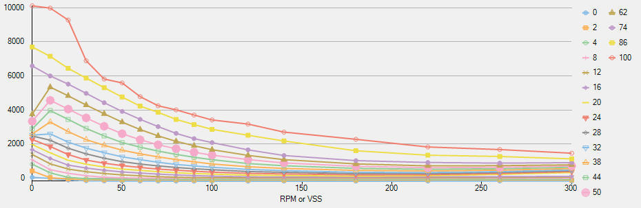
Yes, the graphs look odd. Part of this oddity is the use of speed for the column values, but the graph also reflects the impact of GEARING across the speed range.
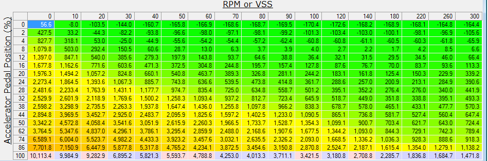
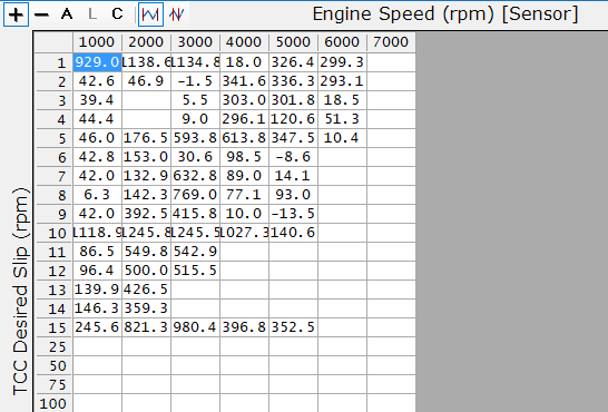
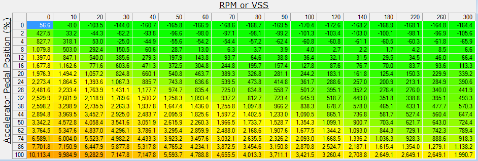
This is the same table with values shown. How do we read this table? The left axis is our pedal position, from 0-100%. So if we are at WOT, the bottom row is the row of interest. Note that not all cars have pedal position =100 at WOT. But to keep it simple, as on my ATS-V, WOT gives a 99.6% pedal position so we are operating near the 100 row.
Okay, so what is happening with the columns? The table can be RPM or VSS(speed) based. The axis here goes from 0 to 300, which suggests speed based. When you see huge numbers like these, the table is axle torque. If we saw 0-7200 numbers it would be a RPM table.
Also, conventional wisdom is this is VSS or vehicle speed in Kilometers per hour, not MPH. For an ATS-V with a max speed of 189 mph, the 300 kph table ties out to 186 mph. So that makes sense.
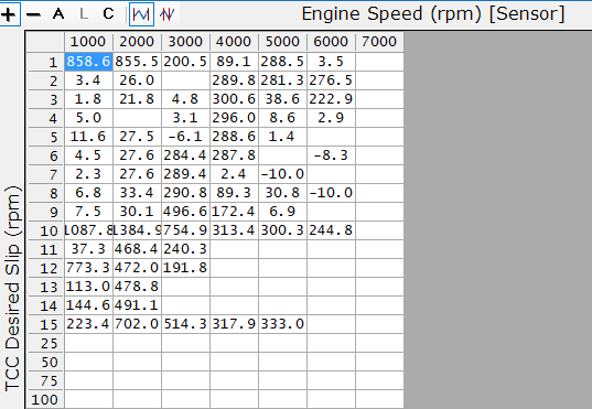
So far so good. Now let’s look at the same table in MPH
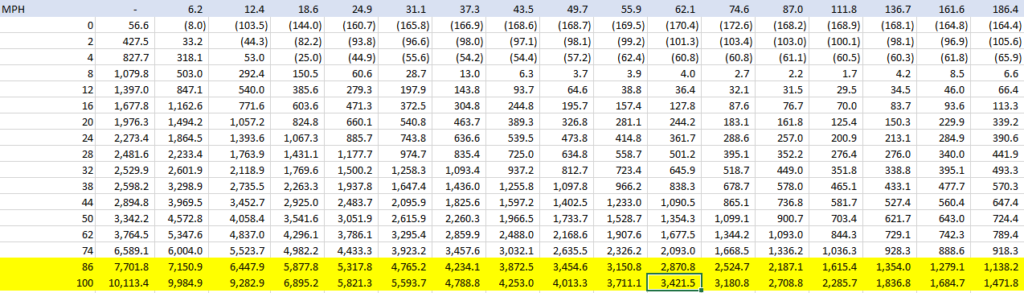
So we can see we go from 10,113 ft lbs of axle torque requested at 0 mph down to 1,471 ft lbs of axle torque at 186 mph.
Okay, but what about engine torque demand? To get to engine torque, we need to consider the tire diameter, the final drive ratio, and each individual gear ratio.
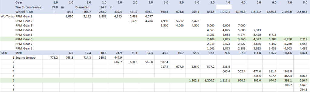
So knowing the speed, and the tire diameter, we can calculate wheel RPM. Knowing the wheel RPM, and the transmission gearing (final drive x gear ratio) we can calculate the RPM for each gear. I have ignored torque converter interaction for this purpose.
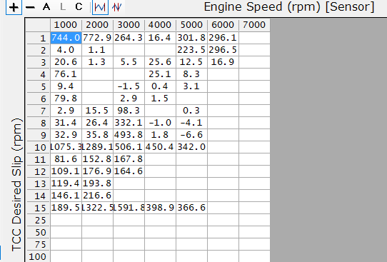
Now this give us a table with engine torque requests (limits) by RPM range.
What we observe is that in 1st gear, the stock table request is for torque from 778 down to 448 ft lbs near the shift point. In 2nd gear, from 688 down to 502 ft lbs.
Why don’t we just max the whole table out from 0-300? That will result in huge torque delta requests; one oddity of the system is that it tends to respond less rapidly to huge requests, (perhaps fearing that they are in error?) So we want to request close to what we actually need.
It also suggests how the requested torque ends up being numbers we don’t find on individual tables — they are calculated from the driver demand and converted to engine torque.
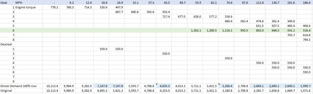
In my case I would like my driver demand to be at least 550 ft lbs minimum at any point. So where I see the driver demand for a gear and RPM would fall under 550, I have inserted a 550 in my ‘desired’ area. The final driver demand table 100% row is then a calculated row showing (blue highlights) the cells that need to be increased, as compared to the original table in the row below (marked ‘Original’).
Not every cell needs to be changed. At higher speeds, where one could be in gear 4, 5, or higher, the RPM needs for the LOWEST numerical gear (highest ratio) assure that the resulting axle torque will also exceed the desired engine torque in each higher (lower ratio) gear at the same speed.
This is the tune G driver demand table I plan for the next test.
What do you think? Please share your experiences on what has worked well, what has not for ATS-V tuning.